Vision-Doctor

Practice

Planning and realization of applications

Recalibration and maintenance of the machine vision system

In practical operation the recognition rate can possibly decrease after a longer period. There may be a large number of reasons, apart from changing inspection parts (!), however, these are often quite simple things that can be eliminated easily.

The prerequisite for a re-calibration is to know the former ideal state which is supposed to be restored. Yet this requires some documentation in advance or some additional inspection tools in your image processing application.

Tools for camera setup and calibration

Documentation of

  • all relevant working distances and angles of the camera to illumination and component
  • f-stop of the lens
  • settings of flash controllers
  • reference images depicting the original state
  • exposure time and gain, etc., unless they were directly stored in the software project

The calibration test chart

A test chart adapted to the application will help the operator to set up the system correctly. It should be able to calibrate all the measured variables of the system to be determined.

Some examples for calibration charts:

  • Square test grid: the lens distortion, but also a possible oblique camera installation can be measured in this way. It also serves to determine a scaling factor if the measurement includes many squares.
  • Measuring circle in the middle: on the basis of a radius measurement, a pixel-millimetre ratio can be calculated very easily.
  • Grey wedges and shade of 50% grey: These patterns serve to check wether all grey values are linearly present and recognisable. Caution: The camera system is subsequently adjusted in such a way that white does NOT have a grey value of 255, but a slight shade of grey. Overexposure is avoided using CCD sensors!
  • Siemens star in the centre and corners: With the help of the Siemens stars, the limiting resolution of the optics and camera system is determined. At the image margins, the optical resolving capacity is always lower!
  • Horizontal and vertical line pairs: they also serve to determine the modulation transfer function (MTF).
  • RGB and CMYK colour model: helpful for calibrating a colour camera.

Calibration using the software

In order to reproduce the same state, some test tools can be integrated in the software project which make it easier for the user to reach the same state as at the beginning.

But which physical parameters can be detected by a camera system? These must be brought back to its initial state by means of calibration:

  • Primary a camera system measures the brightness intensities (I) of each pixel. In the case of an RGB colour camera, these will be intensities per colour channel, i.e. I * R, I * G and I * B. With the help of area-based statistics tools / lightmeters / intensity tools, the vision specialist easily determines the grey values on a reference surface. Now you can restore the image brightness correcting the shutter speed of your camera or lens aperture, etc. In case of a colour camera, not only the overall brightness may shift, but also the weighting of the individual colour channels. Often the camera or evaluation software provides for a white balance functionality.
  • With the help of measuring tools, etc. the X and Y coordinates and orientation of parts can be detected. A small measuring application that calculates the offset and angle between your test object and a reference vector immediately indicates whether the camera still detects the dame inspection field and how far it deviates.
  • Even the Z-coordinates can be calculated using the camera system, although the camera system is primarily only capable to detect X-and Y-dimensions. However, this is nevertheless possible, as soon as the diameter of a test object is known, for instance. Using an entocentric normal lens, the inspected parts appear the smaller, the further away the camera. If you measure, for instance, a circular component and scale the diameter of any random pixel values to 100% in the ideal state, you know immediately whether the camera has moved away from or towards the object. If you see that the Z-axis is misaligned, re-scaling is stringently required.

Using a simple additional measuring application and a brightness measuring tool, the user will be able to adjust the system within seconds in such a way that the intensity, translation, rotation and scaling can be corrected to the initial values.

Coordinate transformation

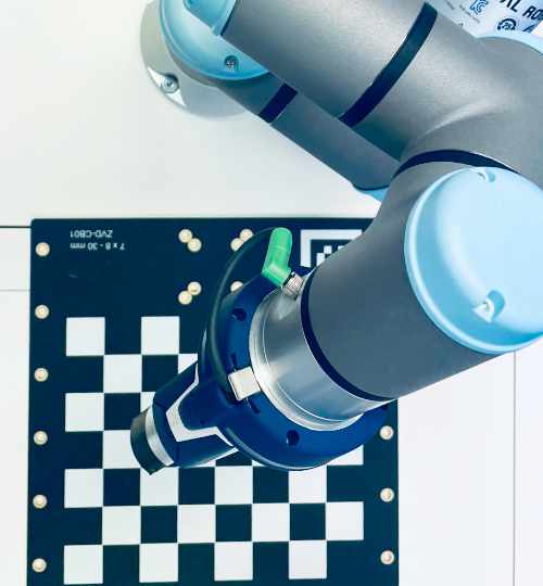
Image processing applications often do not only have features to convert pixels to millimetres, etc., but calibration routines using complex coordinate systems. Multi-point coordinate systems automatically determine the origin, the location of the X-axis and Y-axis and scaling. Complex multi-point or chessboard pattern systems are even capable to compensate nonlinear distortion such as lens or trapezoidal projection errors etc. A perspective distortion can be removed.

This also facilitates the automatic re-calibration significantly. Please note that absolute precision is required for this, too. In case of robot applications please calibrate ideally in the plane of the gripper system and not in the conveyor belt plane. A proper calibration target must be very accurate and precisely positionable by means of pins.

Recalibration and maintenance of the system - a case study

Actual situation: The image looks too dark, the software application is not working properly any more. According to the reference image, however, the current image detail of the camera image is not shifted. What may have happened?

  • Aperture of lens out of adjustment? > Please check the adhesive tape and fixing screws
  • Light-absorbing dirt on the lens?
  • Exposure time of the camera? > Please check values in the software or hardware settings
  • Correct camera gain (electronic amplification)? > Software or hardware settings
  • Flash controller settings for the LED strobing ok?
  • Working distance and installation angle of camera? > Measure and support using software tools
  • Working distance and angle of the lighting? > Manual measurement
  • Dirt on lighting? Defective tube?

Nothing found?

Most likely, the illumination has aged and your light source is no longer as intense as before. How to correct the actual lack of light.

  • Try a temporal (and possibly also permanent) replacement of your lighting, especially when using a halogen or fluorescent lamp
  • Adjust the aperture on the lens (note: you will lose depth of field)
  • Try a longer exposure time (note: motion blurring)
  • Small increase in the camera gain (note: noise will also increase)

Do you require advice?

Vision-Doctor.com is a private, independent, non-commercial website project without customer support.

For the best advice, training and sales of imaging and machine vision equipment please click here.

(external link partner website in Europe)
Kalibration Kamerasystem industrielle Bildverarbeitung