Systems
Line scan camera solutions
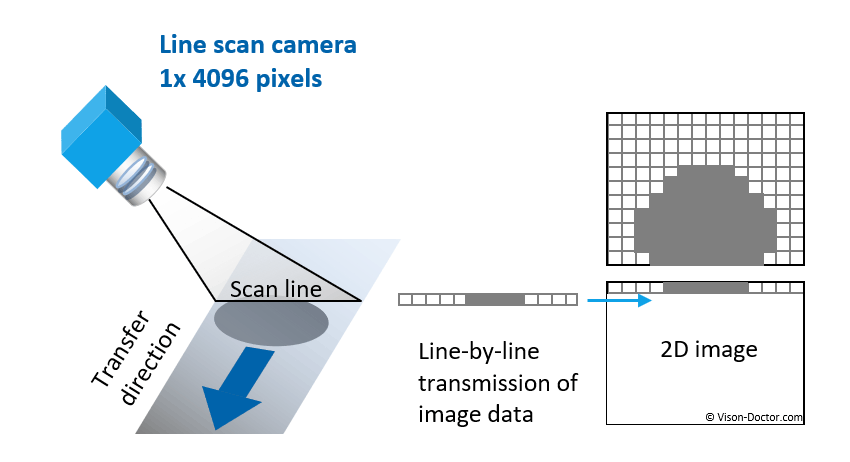
An industrial line scan camera is a special type of camera that has only one line of pixels. Unlike conventional cameras, which have a two-dimensional sensor, a line scan camera only exposes one line at a time.
In order to obtain a two-dimensional image of a surface, several lines are often recorded one after the other in extremely fast time while the camera moves relative to the object. This can be implemented in various ways, e.g. by using a conveyor belt, a linear unit or a robot.
Why line scan cameras?
There are many reasons for using line scan cameras: As a seamless recording method, it is ideal for inspecting longer objects and continuous materials. The price/performance ratio also favours line scan cameras when high resolutions are required. The resolutions range up to 16384 pixels in the X direction and (almost) any resolution in the transport direction.
Typical line scan camera applications:
-
Endless materials such as glass, steel, fabric, paper or foils, such as those used in battery cell production, can be inspected without interruption.
-
Even large and long objects such as flat screens and electronic assemblies can be inspected in high resolution. Typical applications include the inspection of surface defects and print inspection.
-
Line scan cameras are also used for scanning documents and films as well as for mail sorting (OCR, code reading).
-
For inspection of round bodies without perspective distortion. To do this, the component must be rotated. In this way, a true 360-degree inspection of the surface or print image can be realised.

Image creation with line scan cameras
The camera only records one image line at a time in rapid succession. In order to capture a two-dimensional image, the object must be moved for inspection: Either the object to be recorded is moved using a conveyor belt, etc. (the 'fax principle'), or the camera is moved over the stationary object (the 'scanner principle').
As the image in the Y direction is created by the movement of the conveyor belt, it is important that this movement is very constant. Technically, however, this is almost impossible to achieve, so the feed is synchronised using an encoder to avoid image distortion.
If there are individual items on a conveyor belt, image acquisition can also be triggered: A light barrier or other proximity switch sends a signal to the image acquisition hardware. The lines are only captured or transmitted at that moment, and it can be avoided that the part to be inspected is spread over two retracted image blocks.
Line scan cameras can work very quickly (10-400 kHz) so that they can scan moving objects without motion blur. Due to the short exposure time, line scan cameras require bright line illumination.

Classic line scan cameras
As with 2D image acquisition, a classic line scan camera requires a lens and (line) illumination for correct image acquisition.
There are several sensor types available for image capture. Usually a single sensor line is sufficient to produce a monochrome image. However, several monochrome sensor lines (dual line, quad line sensors) can also be used in order to capture the image several times and therefore more brightly. This reduces the amount of lighting required.
The TDI line scan cameras with up to 192 ‘stages’ are a real speciality. The result is extreme light sensitivity, but also image capture from slightly different angles, which has fewer problems with reflections.
The pixels of the multi-line sensors can also be provided with colour filters. In this way, it is possible to build dual line or triple line colour sensors for colour inspections. Quad line sensors with RGB + infrared are also used for multispectral inspection technologies.
Another speciality is line scan cameras with inGaAs detectors, which enable real SWIR applications such as contamination detection on wafers, high temperature thermal imaging inspections, etc.

Compact Image Sensors
Industrial compact image sensors, also known as line scan bars or CIS bars, acquire image information in the same way as classic line scan cameras. They expose one line after the other while the object moves relative to the camera. However, the device has fixed overall lengths and is mounted at a fixed working distance.
A key component of the Compact Image Sensor is the sensor array, which consists of many fixed-width sensor elements arranged next to each other. The sensor pixels are exposed with the aid of integrated optical elements (GRIN cylindrical rod lenses). These enable a distortion-free 1:1 image of the object on the sensor array.
Homogeneous LED lighting is also integrated directly into the sensor housing. The lighting is always optimally aligned with the sensor and there is no need for time-consuming calibration of external light sources.
Advantages of line scan bars / compact image sensors:
-
Thanks to its very compact design, the Compact Image Sensor takes up only a fraction of the space required by systems based on conventional line scan cameras.
-
Compact image sensors offer resolutions of up to 600 or 1200 dpi and deliver crisp, sharp images.
-
The 1:1 depiction creates a telecentric image. This eliminates shadowing and occlusions, especially at the edges. Measurement applications are also easier to realise.
-
Simple installation and maintenance, as this is a complete sensor unit with optics and lighting.

Transmission interfaces
Since the beginning of the millennium, the CameraLink interface has become the standard for image transfer in line scan cameras, completely replacing the old LVDS interface.
This standard can transfer up to 850 megabytes per second.
For less demanding applications, Gigabit Ethernet has established itself as a second transmission medium for bandwidths of up to around 90 megabytes per second. The advantages of network cabling are the elimination of the frame grabber and the long cable lengths that can be achieved using low-cost Ethernet network cables. This makes the overall system much more cost-effective. Today, both transmission methods are increasingly being replaced by new alternatives.
CoaXPress is a high-speed data transmission interface specifically designed for industrial image processing systems. It offers very high data rates of up to 12.5 Gbps per cable and supports long cable lengths of up to 100 metres. A particular advantage of CoaXPress is the bidirectional communication and power supply over the same cable, which simplifies installation and management.
Camera Link HS is an advancement of the Camera Link standard and offers even higher data rates and ranges. CLHS supports data rates of up to 10 Gbps per channel and provides a reliable and stable connection for demanding image processing applications.
5GigE is an extension of the Gigabit Ethernet standard and offers a data transfer rate of up to 5 Gbps. Alternatively, it offers the user 10GigE transfer rates of up to 10 Gbps. Both are increasingly found in industrial line scan cameras as successors to GigE-based systems.
Benefits of Line scan cameras
1. High-resolution scans at an affordable price
2. Ideal for capturing long or continuous materials
3. Ideal for moving objects
4. High scan rates
5. Homogeneously illuminated images
6. No image distortion on cylindrical objects
7. Excellent colour and spectral information
Potential disadvantages
1. Motion always required
2. An encoder is usually required
3. Precise adjustment and robust construction required
4. Often large camera housings
5. Larger sensors need larger lenses
6. Low depth of field
7. High speed data acquisition requires special transmission interfaces
Need help selecting a system?
Vision-Doctor.com is a private, independent, non-commercial homepage project and not a technology provider or system integrator. Suitable technologies and further professional support can be obtained from the companies & partners listed below.
If necessary, I will be happy to provide a quick recommendation, contacts and brief information.


