")


Lookup Tables (LUTs)
LUTs allow the brightness information of each pixel to be translated into a new value. This can be done by creating and describing a table that specifies which grey tone (from 0 to 255 for an 8-bit monochrome camera) is assigned which target value. A LUT is nothing more than a double register. The IN values (0 to 255, i.e. the current grey values of each pixel) are replaced 1:1 by the fixed value of the OUT values (also an array with 256 values).
A wide range of image manipulations can be performed in this way, even if the camera does not have dedicated greyscale functions.

Manual gamma curve correction using LUTs
Dark grey tones in the image are strongly spread out and thus made visible.

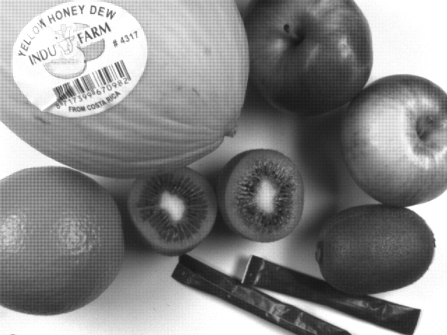
Complete image inversion using La UT
Grey tone distribution was inverted.
Shading correction
Shading correction aims to minimise differences in brightness and colour caused by uneven lighting or optical distortion.
Typical causes are
- Vignetting effects of the camera lens
- Too little or uneven illumination due to a design that does not evenly illuminate the entire image.
- Shading effects caused by microlenses on CMOS sensors that are very large compared to the camera's lens mount (C-mount / F-mount, etc.). Microlenses on the pixels at the edge of the sensor also cause vignetting due to oblique incidence of light. This results in severe image vignetting.
Shading correction can compensate for this light gradient. Modern cameras can do this directly. This functionality is also referred to as bright image calibration, light gradient correction, field of view balance, etc.
This correction is particularly useful in applications where uniform illumination and colour fidelity are critical.

Original image with shading
Strong loss of brightness at the edges due to the ring light being too small. Bright areas with 40% difference in brightness.

Image after shading correction
Shading correction has been applied to the image. Grey tones now appear homogeneous. Hardly any measurable brightness variations in the 3 tool regions.
Bayer8 to RGB conversion
Modern industrial colour cameras can transmit their data in a variety of colour formats. However, the actual colour image produced by a single-chip colour camera is a greyscale Bayer mosaic image. In a typical pixel array on the sensor, colour filters on each pixel allow only red, green or blue light to pass through. The result is a rasterised greyscale image. The brightness of the grey tones corresponds to the intensity of the colour. Taking into account the respective pixel neighbours, the missing R/G/B values can be obtained and calculated for all pixels. Many colour cameras can perform a colour conversion (Bayer-to-RGB conversion) directly using an FPGA.
Raw Bayer image without colour conversion
(Enlarge image!) The RGB colour mosaic on the single-chip colour sensor produces a native greyscale image in which the R/G/B pixels are of different brightness. The image appears rasterised. The colour information can be calculated from this pattern.

Computed colpour image
Image calculated from Bayer image (8 bit) contains 24 bit colour information, but loses detail resolution due to Bayer pattern and has slight misinformation (colour fringes) at object edges.
Instead of a 24-bit RGB digital colour image, the image can often be transmitted as an 8-bit Bayer greyscale raw image. However, colour conversion must then be performed on a frame grabber or using PC software. The advantage of post-conversion is the higher frame rate that can be transmitted, as only 8-bit mono information needs to be transported, rather than 24-bit colour information. If the conversion is done in the camera, neither the frame grabber nor the computer's CPU is stressed.
Need to buy the right camera?
Vision-Doctor.com is a private, independent, non-commercial homepage project and not a technology provider or system integrator. Suitable technologies and further professional support can be obtained from the companies & partners listed below.
If necessary, I will be happy to provide a quick recommendation, contacts and brief information.
