

The machine vision expert is interested in depicting objects with the highest possible resolution (sharpness, detail) and contrast. The image should realistically represent both coarse and fine object structures in all regions of the image. Unfortunately, this is not always possible in practice. It turns out that contrast degradation occurs particularly with fine object structures, so that above a certain fineness the features can no longer be analysed by the software. This loss of image quality also tends to increase from the centre to the edges of the image
The modulation transfer function (MTF) is the most important measure of the resolution of the optics.
These graphs, which can be obtained from the manufacturer, show how many adjacent black and white line pairs can still be distinguished by contrast - in other words, the more line pairs with the highest possible contrast, the better the lens.
The starting point is a test chart with progressively finer structures of black and white bars (line pairs per millimetre) with an ideal maximum object contrast of 100%. The resulting contrast of the individual light-dark patterns can then be measured again in the recorded image.
It can be seen that the contrast in the image steadily decreases as the object structure becomes finer. Pairs of edges that could be described as black and white are later only dark grey-light grey.
In the image of this test sample, the structures become 'flatter' with increasing fineness, and usually also towards the edge of the image. The best optical performance of a lens is usually in the centre of the image. The finest structures, which can only be seen with a 'certain' residual contrast, represent the resolution limit of the lens. The more contrast the lens can deliver with the finest structures, the better it is.

An MTF diagram ultimately plots the measured image contrast against line pairs/mm. However, other forms of visualisation are also possible.

This reduction in contrast is caused by the diffraction of light at the slit. Due to the wave properties of light, which can be described as an electromagnetic wave, special effects occur here. When the electromagnetic wave of light encounters an obstacle, a new wave front is created at the edge, which can also propagate into the geometric shadow space of the obstacle. In the case of lenses, this 'edge' is the circular aperture of the optics and the resulting diffraction patterns are concentric intensity distributions.
The theoretical ideal signal results in an intensity distribution that is essentially a first order Bessel function. This diffraction pattern is also known as an airy disc.


The Rayleigh criterion assumes that two airy disks of the same intensity and colour can still be differentiated when the minimum of the first diffraction coincides with the maximum of the second. Between the two overlapping airy disks, the brightness drops to 75% of the maximum value. This corresponds to a remaining contrast of 14% (of the initial contrast). Two spots can only just be differentiated if in the image their maxima are at least apart by the radius r of the airy disk. In case of lower object contrasts and measuring applications, this information, however, must rather be judged critically.
The radius of the airy disk can be taken as the diffraction-related limiting resolution. There the signal peaks of the diffraction patterns are hardly overlapping, the remaining contrast is correspondingly high. Especially in case of non-ideal starting conditions which do not always provide an initial contrast of 100%, this is a useful assumption.
The radius of the first minimum of the diffraction pattern at the circular aperture is calculated from:
Rmin1 = 1.22 * wavelength of the light * effective focal ratio
The diameter of the diffraction disk is:
d= 2 * 1.22 * wavelength of the light * effective focal ratio
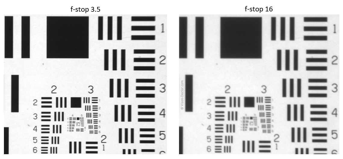
The diameter of the airy disk and thus the theoretic diffraction-related limiting resolution therefore depend on the wavelength, but in particular extremely on the aperture of the optics. From an aperture of 5.6 to 8 on, these values are already greater than the pixel structures of state-of-the-art digital image sensors.

This effect is particularly noticeable when the lens is stopped down.
Despite the high quality of the lens and camera, there is an extreme image degradation when stopped down!

The imaging performance of an optical system is given in an MTF diagram. This is always less than the theoretical limit of the optics due to diffraction effects. The structure fineness (line pairs/mm) is plotted against the image contrast (first figure).
However, the modulation can also be plotted against image height in the same way. As the imaging performance decreases significantly from the optical centre to the edge of the image, this contrast function is particularly popular with optics manufacturers, both in the tangential direction and in the sagittal (=radial) direction to the optical centre of the lens.
Caution: These values refer only to the optical imaging performance of the lens. To analyse the MTF of the whole system, the MTF of the camera must be combined with the MTF of the lens!

The camera's image sensor also has a significant impact on the resolution limit of the overall system.
The theoretical resolution of a camera sensor is described by the Nyquist frequency:
Nyquist frequency= 1 / ( 2*pixel size)
According to the Nyquist sampling theorem, a signal must be sampled at more than twice the frequency to accurately approximate the output signal. Similarly, the sampling theorem applies to images, where the sampling frequency can be specified in pixels or line pairs/mm.
For the individual pixel sizes of the image sensors, this results in significant differences in how many line pairs per millimetre can be resolved, as the pixel sizes of modern camera sensors in industrial image processing range from approximately 2 to 10 µm. This results in a theoretical physical resolution of 4 to 10 µm when imaging the finest structures and a reproduction scale of 1:1.
However, this alone says nothing about measurement accuracy...
A difficult subject! The limiting resolution of the optics and sensor must be multiplied so that the MTF of the whole system is always below the MTF that limits the imaging performance. This can be the Nyquist frequency of the sensor, but also the MFT of the optics. Unfortunately, the average user can rarely determine MTF curves and can only view the resulting images.
In practice, this means that the finest object structures and the transitions of object edges will be slightly blurred. In principle, the image will always show slight grey gradients at the edges of the object, representing these blurred areas.
Even finer structures than 2-5µm are not necessarily visible with a 1:1 image, but under ideal conditions it is possible to measure more precisely than this value using sub-pixeling methods (mathematical interpolation of the grey tones)! A factor of 3 to 4 in accuracy is certainly possible, but this factor depends solely on the quality of the underlying algorithm.
In this case, a sensor with larger pixels, which theoretically has a poorer Nyquist frequency and therefore resolves fewer line pairs per mm, may deliver a much more accurate measurement result due to a higher full-well capacity and lower sensor noise.
Always take the advice and knowledge of an expert in these discussions. Many important details for this discussion cannot necessarily be found in data sheets, and absolute product knowledge is required to compare and ideally combine similar components from different manufacturers. Do your own comprehensive measurement system analysis!
Vision-Doctor.com is a private, independent, non-commercial website project without customer support.
For the best advice and sales of machine vision lenses please click here.
(external link partner website in Europe - All listed lenses can be ordered here)
