Vision-Doctor

Illumination

Illuminate features & make defects visible

Backlight illumination

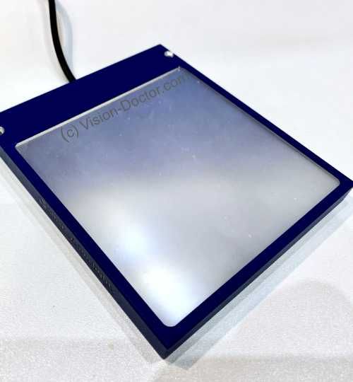
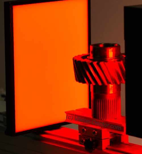
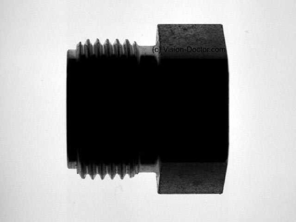
Backlighting is the illumination method of choice when it comes to measuring components as accurately as possible. The lighting is positioned on the opposite side of the camera and the component itself is placed in the beam path.

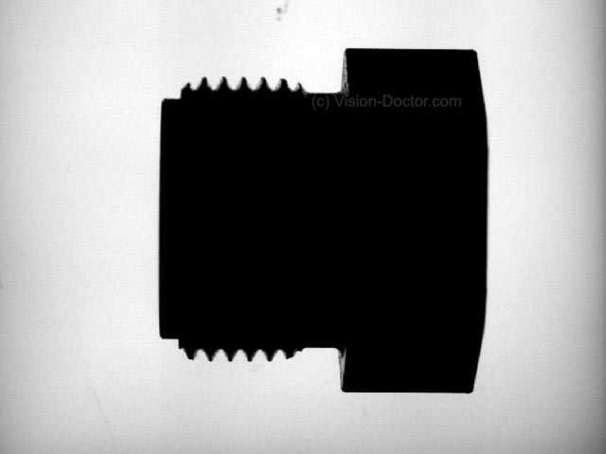
The camera then only sees the component as a black object with its outline. In this way, the external dimensions of the component can be detected very well.

Inspecting and measuring using a backlight

The component can be:

  • on a conveyor belt that is as transparent as possible, but very bright conveyor belts can also be illuminated with red or infrared light.
  • placed on a glass plat. DThis should be tempered glass to minimise scratches on the glass surface.
  • be transported in a guide rail. This is interrupted where the part is supposed to be measured.
  • be held by a robot or gripper system above the light

The component itself is only visible as a silhouette; no further information about the component surface can be obtained. The surface surrounding the component is the illumination into which the camera system looks. This massive excess of light makes the entire application relatively immune to extraneous light.
Halogen lamp in backlight

Be careful: The edges of the image on the left are already clearly shaded. This can lead to measurement inaccuracies when edges in light and dark areas are measured together.

Working principle backlight

Important for Manchine Vision

In order to achieve the best measuring results, background illumination is used which...
  • is as homogeneous as possible over the entire light emitting surface. In this way it is possible to use measurements from the centre towards the margin.
  • emits preferably parallel light, avoiding shade effects at the edges. The higher the contrast difference at the edge, the more accurate the results returned by the image processing software.
  • Never over-exposes the image in measuring applications. Charges migrate into neighbouring pixels which will also be overexposed in this way. The consequence are "thinner" silhouettes, the user gets completely wrong results.
  • An " inspection " on overexposed images sometimes makes sense, if bright blotchy areas are to be overdriven. However, a real calibrated "measuring" in overexposed image regions is no longer possible.

Avoiding stray light with the aid of collimated light

All methods for avoiding stray light lead to sharper and higher-contrast edges in transmitted light, as penumbra effects disappear as edge fringing:

Backlight with diffuse scattered light, close to the object

Part is close to diffuse transmitted light - flanks brightened

Object with backlight using a large working distance

Light 8cm away and therefore appears more directed - Less scattered light - Sharp edges
  • Increase the distance between the backlight and the subject: For example, if the subject is 10 cm away from the lighting instead of 1 cm, penumbra zones are avoided. The diffuse scattered light is simply much weaker than the light shining directly on to the camera and is no longer a factor at a large working distance.
  • Masking the backlight: If a diffuse backlight still needs to be positioned very close, penumbra zones can be avoided by masking the unneeded areas.
  • Using a light control film: a filter plate on the illumination blocks diffuse stray light and passes only vertically emitted light. Half-shade zones are prevented in this way.
  • Use of telecentric backlight illumination: The transmitted light is directed absolutely parallel by an optical lens system. This avoids penumbra. This method should always be used with telecentric lenses and gives the best results.

Increased contrast due to polarisation

By using a polarizing filter on backlight and optics, the test object can be partially darkened by means of the effect of photoelasticity in case of transparent, hard plastics. Particularly highly transparent materials hardly generate any contrast in transmitted light, which is required to find the object or edges. This technique serves to increase the contrast and enhance an evaluation.

    Regular backlight

    Slightly toned transparent part generates low contrast values
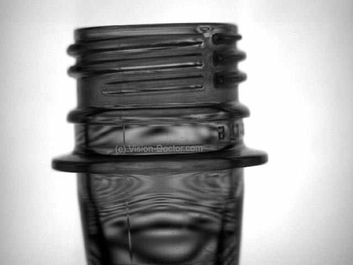
    Polarized backlight

    Backlight with polariziing film and pol. filter on optics creates good contrasts. Mechanical stress distribution visible.

    Contrast enhancement using short-wave light

    Transparent and semi-transparent objects in particular are illuminated in transmitted light, there is hardly any contrast and the test object can hardly be analysed.

    If short-wave light is used, it scatters more than comparable long-wave light due to the shorter wavelength of the light. In this case, the use of blue light instead of red light produced over 10 per cent more contrast.
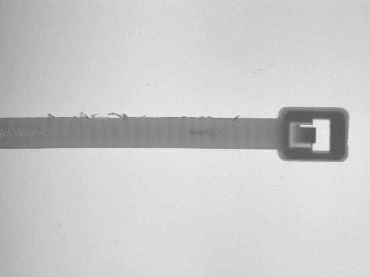
      Red LED backlight

      Semi-transparent cable tie generated brightness contrast of 35 percent measured in the middle of object.

      Blue LED backlight

      Semi-transparent cable tie generated brightness contrast of 47 percent measured in the middle of object with the help of blue light.

      Need machine vision lighting ?

      Vision-Doctor.com is a private, independent, non-commercial homepage project and not a technology provider or system integrator. Suitable technologies and further professional support can be obtained from the companies & partners listed below.

      If necessary, I will be happy to provide a quick recommendation, contacts and brief information.