")


Analogue video signals
For many years analogue image processing systems have been established on the market, which have been replaced by modern cameras with FireWire, USB3 or GigaBit Ethernet interfaces from the beginning to the mid-2000s.
Advantages of analogue video signals and machine vision components
- Extremely wide range of available hardware
- Sophisticated technology, accepted by end customers and available over a long time
- Simple possibility of absolutely synchronous image capture of several cameras by means of frame grabber cards with several on-board A-D converters
- Video data are not sent via a system bus, but by means of a protocol to a frame grabber card. This guarantees high data security and real-time capability.
- Long signal lines > 10 m are no problem
- Lockable plugs and cables, cables suitable for drag chains or robots are available
(The main problem of the USB and 1394a interface are the low cable lengths which are simply too short without the use of repeaters in many applications. Only Gigabit Ethernet makes significant progress in this respect.)
Analogue video standards RS 170 / CCIR, NTSC and PAL
Analogue images can be transmitted according to video standards or undefined standards. Industrial cameras with standard resolution and standard image refresh rates work according to various standards. The common formats from the television technology are RS 170 with 630 x 480 pixels and CCIR common in Europe with 768 x 572 pixels.
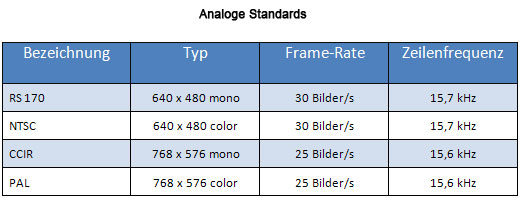
Both standards describe the transmission, signal level and timings of monochrome image data ("black-and-white television") in interlaced mode. In order to reduce the bandwidth, a trick was used. The first half frame only transmits the odd, the next one only the even image lines. Due to the phosphorescent afterglow of the monitor tubes this was enough to achieve sufficient quality. The use of interlaced cameras, however, may lead to significant image interference when capturing moving objects.
The advancement of the television technology soon enhanced the previous standards by colour information. For reasons of compatibility the colour information is transmitted as a colour difference signal in the monochrome signal which is subsequently demodulated into RGB information. RS 170 was extended to NTSC, CCIR to PAL.
In order to transmit the images, a simple coaxial cable with BNC connector can be used, with the complete video signal being transmitted with its image data and its horizontal and vertical sync signals. The cameras are operated in the so-called PLL (phase-locked loop) mode: the frame grabber detects the video cycle of the camera by means of the sync signals and can therefore correctly digitalise the images. As the cameras work in free mode without triggering, the software must wait upon requesting an image until the old image is read out completely and a new image is captured and transmitted. A triggered real-time capable camera acquisition cannot be realised using coaxial cables. The cable lengths using BNC cables dispense with digital sync signals and can therefore in turn be 100 m or longer without difficulty. Like non-standardised video signals, these signals can also be transmitted "in a more intelligent way" by means of Hirose cables (see next section).
Another standard is SVHS which was introduced only in 1987. For the purpose of transmission, brightness and colour signals are separated.
Non-standardised video signals
For many applications the resolutions and image refresh rates listed in the above table are not sufficient. Particularly important for machine vision applications is that moving parts can also be captured without generating interfering image stripes:


Many professional analogue cameras therefore transmit their signals
- not complying with standards in full frame mode (progressive scan) using higher frame rates with resolutions of 640 x 480 pixels to approximately 1600 x 1200 pixels.
- not using BNC cables, but Hirose cables which can also transmit additional synchronisation signals.
For better synchronisation, horizontal and vertical syncs as well as a pixel clock can be transmitted to the frame grabber in addition to the actual video signal using additional data lines in order to provide for a better digitalisation of the image. Especially the image synchronisation of several cameras using one frame grabber can be guaranteed much better in this way, it is a clear plus compared to the other digital interfaces such as USB or FireWire. Yet no extremely long cable lengths can be realised when transmitting the additional signals, from 10 m on there can be difficulties.
A 12-pin round-pole connector produced by the company "Hirose" prevails which has a very compact design and is lockable. Usually the voltage supply is integrated into the Hirose cable so that the cameras can be operated using one single cable today. The pin assignment of the Hirose cable can vary from manufacturer to manufacturer. In the form of the EIA-J standard by Sony, a consistent pin assignment for voltage supply, video signal and control lines has become prevalent in recent years, resulting in a simplification for the user and avoiding damage to the camera.
A 12-pin round-pole connector produced by the company "Hirose" prevails which has a very compact design and is lockable. Usually the voltage supply is integrated into the Hirose cable so that the cameras can be operated using one single cable today. The pin assignment of the Hirose cable can vary from manufacturer to manufacturer. In the form of the EIA-J standard by Sony, a consistent pin assignment for voltage supply, video signal and control lines has become prevalent in recent years, resulting in a simplification for the user and avoiding damage to the camera.
Disadvantages of the analogue video technology
- Additional hardware in the form of frame grabber cards are always required which only provide connection sockets for 1 to maximally 4 or 8 cameras. In order to control more cameras, several frame grabbers or multiplexers (change-over switches) must be used.
- Frame grabber cards and high-quality Hirose cables incur significant additional costs.
- No digital signals are sent, the frame grabber must reconstruct digital values from the analogue video signal. Without transmitting horizontal & vertical syncs and the pixel clock signal, a jitter of at least 0.2 pixels must be expected.
- The cameras cannot be detected and configured directly. Each industrial analogue camera must be configured individually using dip switches or a serial interface. The configuration possibilities are not standardised.
- Cameras which exceed the analogue standards (full frame, higher resolution) require individual configuration files to describe the video timing. The configuration possibilities of the respective cameras are not standardised.
Conclusion:
For decades the analogue interface was the most widely used way to transmit images. The use of a frame grabber guarantees high data security and allows for a synchronous image acquisition in a very simple way when using several cameras. Digital interfaces, however, offer further important functionalities in addition to loss-free image transmission such as configuration possibilities for the camera directly via the software so that this technology was nearly completely replaced with cameras using digital interfaces.